A Brief Overview of Troughed Conveyors
The conveyor is one of the cornerstones of any modern mining operation, providing a safe and reliable way to transport ore from one place to the other, provided that it is a relatively short distance. Although for most industries the flat conveyor belt is the most commonly used, the mining industry tends to use troughed belt conveyors. This type of conveyor lifts up the sides of the normally flat conveyor belt, forming a trough that allows a much larger holding capacity for loose ores with minimal risk of said ores falling off the belt, which happens much more often on a flat conveyor belt. In this article we will be discussing and familiarising ourselves with the important bits of this crucial component and it is always advisable to speak with an expert when it comes to information regarding conveyors.
Before we get to our actual diagram however, there is an important detail that needs to be cleared up. Although the diagram we will be showing below is one of a conveyor belt that is used in the real world, manufacturers design these conveyors with different specifications to suit certain workloads. Some of the most common variations can be found in the dimensions of the conveyor belt, the angle of the trough, the power of the drive motor, the sizes of the pulleys, and the type of takeup mechanism.

Feed Chute: Loose ore and rocks enter through the feed chute and drop down onto the conveyor belt.
Loading Skirts: The loading skirts guide the ores entering through the feed chute from falling out of the conveyor belt.
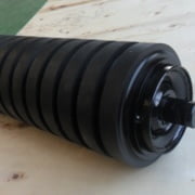
Troughing Carrying Idlers: As the name implies, troughing carrying idlers are set at a specific angle to lift up the sides of the conveyor belt to create the trough shape, and help bear the load of ores and rocks.
Troughed Conveyor Belt: With the help of the troughing idlers, the conveyor belt is shaped to form the distinct trough shape.
Discharge Chute: Objects on the conveyor belt drop through this chute at the end of the conveyor belt, guiding them to the next area.
Head Pulley and Drive: The head pulley is located at the end point of the conveyor belt and is powered by the drive motor.
Snub Pulley: The snub pulley is a secondary pulley placed not too far from the head pulley, the purpose of which is to increase the tension on the conveyor belt at that point, which reduces the amount of power needed for the drive motor to move the belt, improving efficiency and reducing energy costs.
Return Idlers: These idlers help return the conveyor belt into its original flat shape and guides it to the tail pulley.
Stringer: The stringer is the general frame of the conveyor belt to which all of the pulley shafts are mounted.
Closely Spaced Idlers at Loading Point: Because heavy ores and rocks drop vertically through the feed chute and onto the conveyor belt, there are more idlers at the area of impact to spread the weight throughout a larger area, reducing the amount of wear on the idlers. In most cases there are specially-designed idlers called impact idlers, which have a distinct shape designed to absorb more impact than standard idlers.
Horizontal Screw Take-up: The takeup mechanism maintains tension at the tail end of the conveyor to make sure that the conveyor belt is guided correctly as it returns to the top side.
Tail Pulley: Located near the feed chute, the tail pulley guides the conveyor belt back up to the top side, repeating the cycle.


