
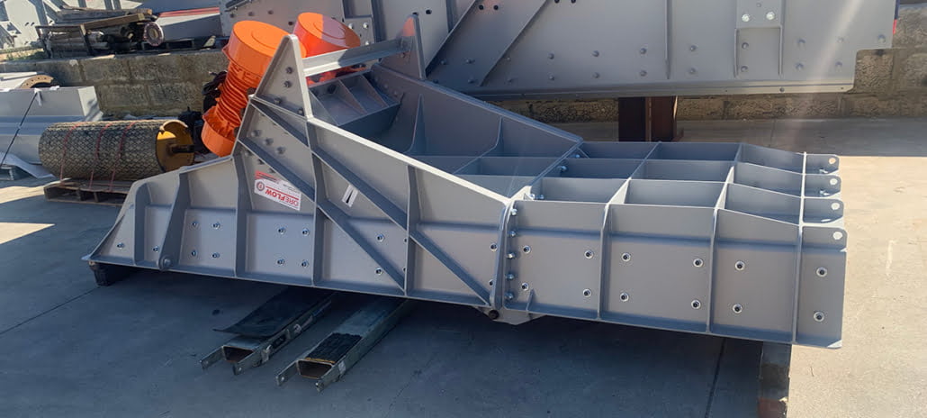
Vibrating Feeders for Mining and Mineral Processing

Vibration-driven feeders for regulated transfer into crushers, screens, conveyors, hoppers and chutes.

REGULATED FEED BY VIBRATION

Helps regulate the feed of material through the trough for steadier transfer.

MATCHED TO THE FEED POINT

Trough size, stroke, drive layout and isolation are considered around the duty.

SUPPORTED BEYOND SUPPLY

Engineering, manufacturing, spare parts and project support from one team.

Vibration-Driven Feeding for Process Transfer Points

Oreflow designs and manufactures vibrating feeders for mining, mineral processing and bulk materials handling applications where material needs to be moved, metered or presented consistently.

A vibrating feeder uses controlled vibration to move material along a trough or tray. This makes it suitable for transfer points where the feed rate, material behaviour, discharge position and receiving equipment all need to be considered together.

Unlike apron feeders, vibrating feeders do not rely on a chain and pan arrangement for heavy impact hopper withdrawal. Unlike belt feeders, they do not use a belt to withdraw and carry material. Their role is focused on vibration-driven feed control, material presentation and consistent transfer into the next stage of the plant.

Designed and manufactured in Western Australia, Oreflow vibrating feeders can be supplied for new plants, plant upgrades, replacement projects and selected refurbishment requirements.

Where Vibration-Based Feeding Works Best

Vibrating feeders are commonly used where material needs to be advanced in a controlled manner before crushing, screening, conveying or further processing.

Crusher Feed

Used to present material into crushing circuits where feed consistency, discharge location and transfer control are important.

Screen Feed

Used to distribute material onto vibrating screens so the feed is presented more evenly across the screen surface.

Conveyor Transfer

Used where material needs to discharge onto conveyors at a regulated rate to support stable transfer through the plant.

Hopper, Bin and Chute Discharge

Used to assist material movement from storage points or transfer points where the plant layout requires controlled discharge.

Upgrade Projects

Configured to suit existing plant footprints where a feeder needs to be replaced, modified or integrated into surrounding equipment.

From Material Flow to Vibrating Feeder Configuration

Specifying a vibrating feeder starts with understanding how material enters the tray, how it needs to move and how it transfers into the next stage of the plant.

Oreflow uses these details to help determine the feeder size, tray profile, drive arrangement, motor selection, support structure, discharge height and maintenance access before manufacture.

Material Behaviour

Particle size, bulk density, moisture content, abrasiveness, stickiness and flow behaviour help determine the feeder duty and tray arrangement.

Feed Rate and Control

Required capacity, controlled discharge rate, operating duty and surge requirements help define feeder size and drive requirements.

Loading Conditions

Drop height, hopper arrangement, bin geometry and impact loading influence tray construction, support structure and wear areas.

Tray and Drive Arrangement

Feeder width, length, tray profile, motor arrangement, drive selection and discharge height are specified around the operating duty.

Downstream Interface

The feeder needs to align with crushers, screens, conveyors, chutes, hoppers and surrounding plant equipment.

Access and Support

Inspection access, motor access, spring access, wear component replacement and spare parts requirements are considered before final layout.

Defining the Vibrating Feeder Duty Before Manufacture

A vibrating feeder needs to be specified around how material enters the trough, how it behaves under vibration and how it needs to discharge into the next stage of the process.

Oreflow considers the required feed rate, material characteristics, loading arrangement, trough profile, vibration drive arrangement, support structure, isolation requirements and maintenance access before manufacture.

Specification Area

What Oreflow Considers

Feed rate and operating duty

Required throughput, feed control expectations, operating hours and surge requirements.

Material characteristics

Particle size, bulk density, moisture content, abrasiveness, stickiness and general flow behaviour.

Inlet and Loading Arrangement

Hopper, bin, chute or transfer point layout, including loading direction, drop height and impact areas.

Trough Design

Feeder width, length, depth, discharge profile, liner requirements and wear areas.

Vibration Drive Arrangement

Drive layout, stroke requirements, motor arrangement and out-of-balance motor suitability where applicable.

Support & Isolation

Spring arrangement, base structure, support frame, vibration isolation and surrounding plant constraints.

Plant Interface

Alignment with crushers, screens, conveyors, hoppers, chutes and other receiving equipment.

Access & Maintainability

Access to motors, springs, liners, guarding, inspection points and replacement components.

Manufacture, Replacement and Vibrating Feeder Support

Oreflow supports vibrating feeder projects from initial layout and manufacture through to selected spare parts, repairs and refurbishment requirements.

For new equipment, Oreflow can manufacture vibrating feeders to suit the required feed rate, trough arrangement, vibration drive layout, support structure and plant interface.

For existing equipment, Oreflow can assist with selected replacement, modification and refurbishment scopes depending on the feeder condition, component requirements and available site information.

Support can include guidance around trough liners, springs, motors, guarding, access improvements and replacement components where suited to the feeder design and project scope.

FAQs

Vibrating feeders are used to move, meter or present material into crushers, screens, conveyors, hoppers, chutes and processing equipment.

A vibrating feeder is commonly used where material needs to be transferred at a regulated rate and presented consistently into the next stage of the plant.

Yes. Oreflow can configure vibrating feeders around material characteristics, feed rate, tray arrangement, drive layout, plant layout, loading conditions and maintenance access requirements.

Vibrating feeders use vibration-driven trough movement. Belt feeders use a belt to withdraw and transfer material, making belt tracking, skirting and conveyor loading key parts of their design.

Vibrating feeders are mainly used for controlled feeding and transfer. Grizzly feeders include a grizzly section that allows fines or smaller material to separate from oversize material before the next process stage.

Yes. Oreflow can configure vibrating feeders around the available footprint, material characteristics, feed rate, trough layout, drive arrangement and surrounding plant equipment.

Useful information includes material type, particle size, bulk density, moisture content, target feed rate, loading method, trough requirements, receiving equipment, available space and maintenance access requirements.

Yes. Oreflow can support selected spare parts, repairs, modifications and refurbishment requirements depending on the feeder design, condition and project scope.

Related Products

Configure a Vibrating Feeder for Your Transfer Point

Oreflow can help design, manufacture or support a vibrating feeder suited to your material, feed rate, trough arrangement, drive layout and plant interface.